RS485 Protocol Tutorial: A Comprehensive Guide
Hello, fellow tech enthusiasts! In this blog post, I will introduce you to RS485 Protocol, one of the most widely used communication protocols in industrial and embedded systems. RS485 enables reliable, long-distance, and high-speed data transmission between multiple devices over a shared bus. This protocol is essential for building robust networks in environments like automation, instrumentation, and control systems. In this tutorial, we’ll explore the key features of RS485, its wiring and topology, configuration tips, and how to implement it in real-world applications. By the end of this guide, you will have a clear understanding of how RS485 works and how to leverage it effectively in your projects. Let’s dive in!
Table of contents
- RS485 Protocol Tutorial: A Comprehensive Guide
- Introduction to RS485 Protocol
- Key Characteristics of RS485:
- Key Features of RS485
- Components of RS485 Communication System
- Working Principle of RS485 Protocol
- RS485 vs. RS232
- Common RS485 Connectors
- Advantages of RS485 Protocol
- Disadvantages of RS485 Protocol
- Future Development and Enhancement of RS485 Protocol
Introduction to RS485 Protocol
RS485 is a robust and versatile communication protocol widely used in industrial and embedded systems. Known for its ability to support long-distance and high-speed data transmission, RS485 enables multiple devices to communicate over a single bus efficiently. Unlike its predecessors, RS485 supports differential signaling, making it highly resistant to noise and interference, even in harsh environments. Its ability to facilitate half-duplex or full-duplex communication makes it ideal for applications like automation, control systems, and instrumentation. With support for up to 32 devices on a single network, RS485 is a preferred choice for scalable and reliable communication. In this guide, we’ll uncover the fundamentals of RS485, its advantages, and its practical applications.

What is RS485 Protocol?
RS485 is a widely used communication protocol defined by the TIA/EIA-485 standard. It is designed for serial communication that enables reliable data transfer over long distances and in electrically noisy environments. RS485 is commonly employed in industrial automation, embedded systems, and instrumentation, where robust and efficient communication between multiple devices is essential.

Key Characteristics of RS485:
Following are the Characteristics of RS485:
1. Differential Signaling
RS485 uses differential signaling, meaning it transmits data over two wires (A and B) instead of a single-ended signal. This approach ensures high immunity to electromagnetic interference (EMI) and allows for reliable communication even in noisy environments.
2. Multi-Device Communication
RS485 supports multi-drop configurations, allowing up to 32 devices (drivers and receivers) on the same communication bus. Modern RS485 transceivers often extend this limit to 128 or more devices.
3. Long-Distance Communication
With its robust signaling mechanism, RS485 can transmit data over distances up to 1200 meters (4000 feet) at lower baud rates. For higher baud rates, the effective range decreases, but it still outperforms other protocols like RS232.
4. Half-Duplex and Full-Duplex Modes
RS485 supports half-duplex communication by default, where data transmission and reception occur on the same wires but not simultaneously. For applications requiring simultaneous communication, full-duplex mode can be achieved using additional wiring.
5. Baud Rates
RS485 supports a wide range of baud rates, typically from 300 bps to 10 Mbps, making it versatile for various applications requiring either high speed or long-distance communication.
Key Features of RS485
The RS485 protocol is packed with features that make it ideal for robust, long-distance, and multi-device communication in industrial and embedded environments. Here is a detailed explanation of its key features:
1. Differential Signaling
RS485 uses differential signaling to transmit data, meaning it sends signals over two wires (labeled as A and B) instead of one. In this method:
- A logic “1” is represented by a positive voltage difference between the two wires.
- A logic “0” is represented by a negative voltage difference between the two wires.
This approach provides high immunity to electromagnetic interference (EMI) because any external noise affecting the wires will induce the same voltage on both, and the differential nature cancels out the noise. This makes RS485 highly reliable, even in electrically noisy industrial environments.
2. Multi-Drop Capability
RS485 supports multi-drop or multi-point communication, enabling multiple devices to share a single communication bus.
- Up to 32 devices (drivers and receivers combined) can be connected to the same RS485 bus.
- Modern transceivers extend this limit to 128 or more devices, depending on the hardware.
This feature reduces wiring complexity and cost, making RS485 ideal for systems where multiple sensors, actuators, or controllers need to communicate.
3. Long-Distance Communication
One of RS485’s standout features is its ability to transmit data reliably over long distances.
- It can support transmission distances of up to 1200 meters (4000 feet) at low baud rates (e.g., 9600 bps).
- At higher baud rates (e.g., 1 Mbps or 10 Mbps), the distance is reduced but remains sufficient for most applications.
This makes RS485 a preferred choice for communication in large facilities, outdoor installations, and across manufacturing floors.
4. High Noise Immunity
The differential signaling mechanism not only ensures long-distance communication but also provides excellent noise immunity. This makes RS485 suitable for environments with high electrical noise, such as factories, power plants, or areas with heavy machinery.
5. Half-Duplex Communication
RS485 typically operates in half-duplex mode, meaning devices can either transmit or receive data, but not both simultaneously.
- Half-duplex operation uses just two wires for data transfer (A and B), reducing the overall wiring cost.
- To avoid conflicts, devices on the bus use protocols like Modbus RTU to coordinate transmission.
For applications requiring simultaneous communication, full-duplex mode can be achieved with an additional pair of wires.
6. Wide Baud Rate Range
RS485 supports a broad range of baud rates, typically from 300 bps to 10 Mbps.
- Lower baud rates are ideal for long-distance communication.
- Higher baud rates are used for applications requiring fast data transfer over shorter distances.
This flexibility allows RS485 to be tailored to various applications, from slow control systems to high-speed data transfers.
7. Compatibility with Standard UARTs
RS485 is compatible with the UART (Universal Asynchronous Receiver-Transmitter) hardware found in most microcontrollers and processors. This simplifies its integration into embedded systems and reduces the need for specialized hardware.
8. Multi-Device Topology Options
RS485 networks support various topology configurations, including:
- Linear Bus: The most common layout, with devices connected along a single bus.
- Star or Tree Configurations: Achievable using repeaters, though not recommended due to potential signal reflections.
The flexibility of topology makes RS485 adaptable to different physical layouts.
9. Simple and Cost-Effective Implementation
RS485 requires minimal wiring and hardware to set up.
- A typical RS485 bus uses only two wires for half-duplex communication, and optional two more wires for full-duplex setups.
- It is an economical choice for industrial and embedded systems, where robustness and simplicity are key requirements.
10. Supports Wide Voltage Ranges
RS485 transceivers typically operate within a wide voltage range, such as -7V to +12V, ensuring reliable communication even when there are slight mismatches in ground potential between devices.
11. Protocol Independence
RS485 is a physical layer standard and does not dictate the communication protocol used. Common protocols implemented over RS485 include:
- Modbus RTU: Modbus RTU is a master-slave communication protocol commonly used in industrial automation, transmitting data in a compact binary format over RS485. It ensures reliable communication with error checking via CRC.
- Profibus: Profibus (Process Field Bus) is a high-speed industrial communication protocol for real-time data exchange, supporting multi-master and slave communication in factory and process automation.
- DMX512: (used in stage lighting control) This versatility allows RS485 to support a wide range of applications.
Components of RS485 Communication System
An RS485 communication system comprises various hardware and software components that work together to enable efficient and reliable data transfer. These components are essential for setting up, configuring, and maintaining an RS485 network. Here’s a detailed explanation of each:
1. RS485 Transceivers
The RS485 transceiver is the core component responsible for converting data signals between the UART (Universal Asynchronous Receiver-Transmitter) of a device and the differential RS485 bus.
- Driver (Transmitter): Sends data over the RS485 differential pair (A and B wires). It converts single-ended signals into differential signals.
- Receiver: Detects the differential signals from the RS485 bus and converts them into single-ended signals for the UART to process.
- Modern RS485 transceivers offer features like:
- Fail-safe biasing to prevent erroneous data when the bus is idle.
- Overload protection against electrical faults.
- Extended device limits (allowing more than 32 devices on the bus).
2. RS485 Bus (Differential Pair)
The RS485 bus consists of two wires, typically labeled A and B, that carry the differential signals. Key attributes of the RS485 bus include:
- Twisted Pair Wires: Twisting minimizes electromagnetic interference (EMI) and crosstalk.
- Shielding (Optional): In noisy environments, shielding further reduces interference.
- Termination Resistors: Placed at both ends of the bus to prevent signal reflections and ensure signal integrity. A typical termination resistor value is 120 ohms, matching the impedance of the cable.
3. Master Device
The master device is the central controller in an RS485 network. It initiates communication by sending requests to one or more slave devices.
- The master can be a PLC, microcontroller, or a computer equipped with an RS485 interface.
- It coordinates the data flow, ensuring no collisions occur on the shared bus.
4. Slave Devices
Slave devices respond to requests from the master. In a multi-drop RS485 network, there can be multiple slaves, each with a unique address.
- Examples of slave devices include sensors, actuators, motor controllers, and display units.
- Slaves remain silent unless the master addresses them, ensuring orderly communication.
5. UART (Universal Asynchronous Receiver-Transmitter)
UART is the interface between the RS485 transceiver and the processing unit (e.g., microcontroller or PLC). It handles:
- Data Serialization/Deserialization: Converts parallel data into serial format for transmission and vice versa.
- Baud Rate Configuration: Determines the speed of communication between devices.
6. Communication Protocol
While RS485 defines the physical layer, a protocol is required for logical communication. Popular protocols over RS485 include:
- Modbus RTU: Widely used in industrial automation.
- Profibus DP: Common in process control and factory automation.
- DMX512: Used for lighting control in theaters and events.
Protocols define rules for addressing, data framing, and error checking.
7. Power Supply
All devices on the RS485 network require a power supply to operate. Key considerations include:
- Voltage Levels: Typically 5V or 3.3V for transceivers, with some industrial devices supporting higher voltages.
- Isolation: Galvanic isolation may be used to protect devices from ground loops and voltage surges.
8. Connectors and Cables
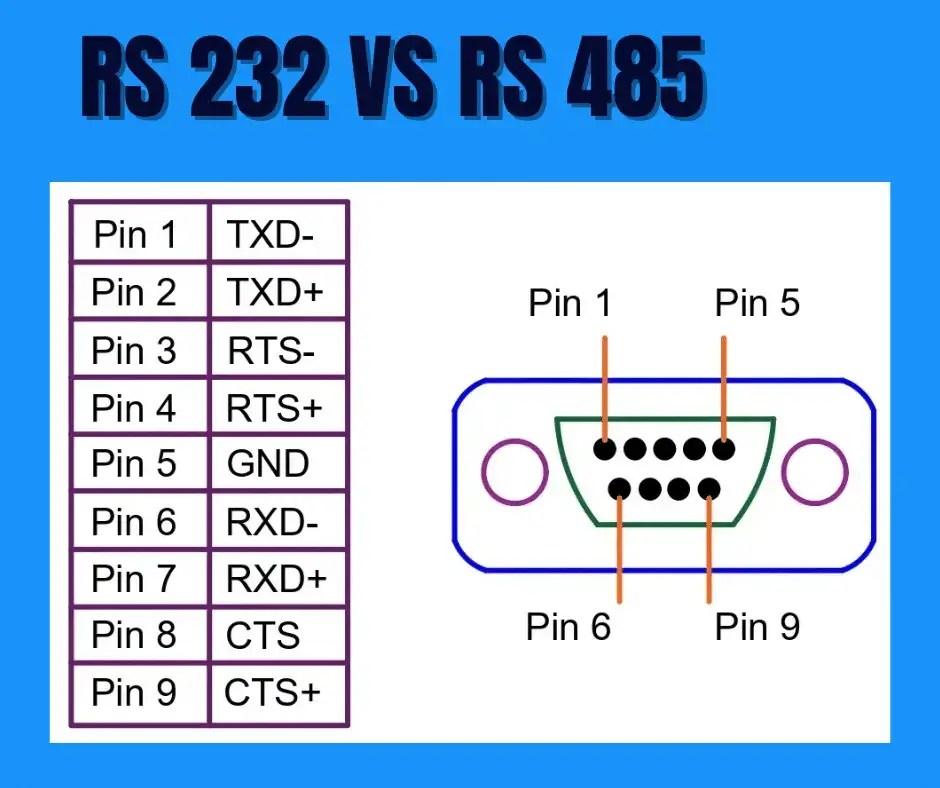
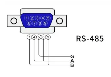
- Connectors: RS485 networks use various connectors, such as DB9, terminal blocks, or custom screw terminals, depending on the application.
- Cables: Shielded twisted-pair cables are standard for RS485. The cable’s impedance should match the termination resistor value (e.g., 120 ohms).
9. Termination and Biasing Resistors
- Termination Resistors: Located at both ends of the RS485 bus to prevent signal reflections and maintain signal quality.
- Biasing Resistors: Pull-up and pull-down resistors ensure a defined voltage level on the bus when no device is transmitting. These resistors prevent the bus from floating, which could lead to erroneous signals.
10. Repeaters (Optional)
For long-distance communication or large networks with many devices, RS485 repeaters can amplify and regenerate signals. Repeaters are used to:
- Extend the communication range.
- Connect multiple RS485 networks.
- Improve signal integrity in noisy environments.
11. Ground Wire (Optional)
In some installations, a dedicated ground wire is used to ensure a common reference voltage between all devices. This reduces potential differences and prevents communication issues.
12. Software Drivers and Tools
To configure and manage the RS485 network, software components are essential:
- Device Drivers: Enable the master device to communicate with the transceiver.
- Diagnostic Tools: Help monitor and troubleshoot the network for errors or performance issues.

You must be logged in to post a comment.